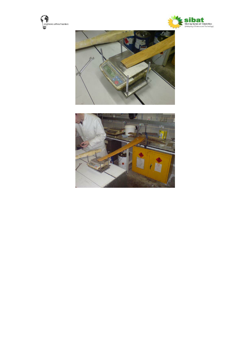
The blade in contact with the scales
The overall the set up
2. The threaded rod is screwed into tapped holes in the base plate, and
locked off to prevent further motion.
3. Clamp the root securely, ensuring that the root does not move when a
force is applied to the tip.
4. Place the rig under the tip of the blade
5. Raise the top plate (with scales resting on it) by adjusting the nuts until
a small force registers on the scales (this force should be close to zero,
but large enough to register on the scales). Record the force displayed
and the distance between the base plate and top plate as close as
possible to the four pieces of threaded rod. This should be done with
calipers if possible.
6. Raise the top plate until the scales register a force of 2N, and repeat
the four measurements at the corners.
7. Repeat these measurements every 2N to an acceptable point, in our
case, we measured up to 10N.
8. Find the deflection of the tip from the readings. If the tip is exactly in the
centre of the four threaded rods take the average value. If not, follow
steps 8 a) and b).
a) Take the measurements shown below.
41